
Design of a Schönflies Motion Generator
Prologue - applications in industry
Schönflies Motion Generators (SMGs) are widely used in many types of factories, particularly for pick-and-place operations. Like many parallel robots, their architecture determines and constrains their motion, resulting in high operational stability and stiffness. Moreover, they have the key advantages of parallel mechanisms, including low moving inertia and high acceleration capability. These characteristics make SMGs attractive for demanding applications such as assembly, packaging, sorting, and electronics manufacturing, where high throughput, repeatability, and positional accuracy are critical.
The videos below show some applications of SMGs in the industry.
Project overview
This project focused on the conceptual design, kinematic synthesis, and optimisation of a 4-DOF parallel Schönflies Motion Generator (SMG) for high-speed pick-and-place applications. The objective was to combine the high stiffness, low moving inertia, and dynamic performance of a parallel manipulator with the 3T1R motion required by SCARA-type industrial tasks: three translational degrees of freedom and one rotation about a fixed vertical axis.
The complete project paper and all the derivations can be found here.
Demonstrated skills: Manipulator design, optimisation, kinematic modelling, MATLAB, SOLIDWORKS
Design objectives
The proposed manipulator is designed to execute a prescribed test trajectory commonly used for benchmarking the dynamic and positional performance of SCARA-type robots. This trajectory includes a combination of planar translations, vertical motion, and orientation changes representative of typical industrial handling tasks.
The design specifications are as follows:
The robot must be capable of producing a test cycle that is commonly accepted for SCARA systems, in at most 500 ms. The test cycle consists of:
25 mm vertical displacement up
300 mm horizontal displacement with a concomitant 90° turn
25 mm vertical displacement down
25 mm vertical displacement up
300 mm horizontal displacement with a reversed 90° turn
25 mm vertical displacement down
The system should be kinetostatically robust. Its forward and inverse Jacobian matrices should have a maximum condition number, k, of 10.
The mechanism should not be too bulky.
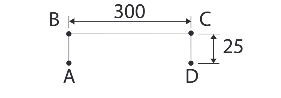
End effector path for manipulator design and performance evaluation
Architecture selection
Several candidate parallel architectures were evaluated before selecting a four-limb, parallel-axis architecture using RUU-type limbs. The selected topology was favoured because it allows the actuators to remain base-mounted, reducing moving mass and rotational inertia, while its geometry helps suppress parasitic platform motions. Four of the five revolute joints in each limb can also be represented as universal joints, substantially simplifying both the mechanical implementation and the mathematical model. This reduces the optimisation problem from six variables to four primary design variables.

Selected architecture
The kinematic relations between the velocities of the moving platform in Cartesian space and the joint velocities were obtained using screw theory. The figure below shows a single limb of the parallel system. As all limbs are identical, the kinematics of a single limb can be easily extended to the entire system.
Kinematic analysis

Schematic of a single manipulator limb
Following screw theory, the following kinematic model is obtained:

Inverse geometry
The inverse geometric model was developed by exploiting the geometry of each RUU limb. The position of the intermediate joint Bᵢ is obtained from the intersection of a circle of radius l₁ and the planar projection of a sphere of radius l₂. Solving the resulting quadratic provides the possible joint configurations, after which the actuated joint angle can be calculated. The formulation can produce up to 16 working modes, requiring careful selection to avoid singular configurations.

Modelling the inverse geometry of a limb

Intersection of the circle and sphere
After simplifying the resulting equations, we obtain the joint angle, qᵢ₁, corresponding to an end-effector pose:

Design optimisation
The design optimisation sought to minimise moving mass while maintaining a usable, well-conditioned workspace. The benchmark trajectory was defined by four Cartesian poses (A, B, C, and D) as shown in the figure below. These four coordinates define the required pick-and-place workspace and are expressed as a function of the design variables—the workspace shifts with the manipulator design parameters, which keeps its relative position to the robot constant.


Operational workspace of the manipulator
Geometric constraints were imposed to prevent limb interference and reduce the likelihood of parallel singularities. A further constraint required the Jacobian condition number to be less than 10 to maintain acceptable kinematic conditioning over the complete trajectory.
Because the translational and rotational components of the Jacobian have different physical units, a characteristic length was introduced to normalise the Jacobian before calculating its condition number. This provided a consistent measure of manipulability and proximity to singular configurations during optimisation.
The optimisation was implemented as an iterative process: candidate geometries were generated, inverse kinematics were evaluated across the complete trajectory, geometric feasibility was checked, and the Jacobian conditioning was calculated before accepting a design. The optimisation problem is expressed as:

Where mₜ is the total mass, l₁ is the length of the proximal link, R is the radius of the base platform, r is the radius of the moving platform, and k(J) is the condition number of the kinematic Jacobian matrix
Resulting design
After several iterations of the algorithm with different initial values and path parameters, the best feasible design found had: R = 477.31 mm, r = 218.15 mm, l₁ = 259.16 mm, l₂ = 379.51 mm, The resulting maximum condition number along the benchmark path was k(J) = 27.52. Although this did not satisfy the target k(J) < 10, its small value indicates that the resulting design has high dexterity throughout the defined workspace.
Implementation of the model
The design was implemented in SOLIDWORKS, where a single symmetric limb was modelled and replicated to create the complete four-limb manipulator. CAD motion and interference analysis were used to verify limb collision avoidance, singularity-related geometric constraints, and the ability of the manipulator to generate the required 3T1R motion.
For trajectory generation, the four Cartesian waypoints were interpolated using Piecewise Cubic Hermite Interpolating Polynomials (PCHIP). Unlike conventional cubic splines, PCHIP avoids overshoot and preserves the bounds of the original waypoints, reducing the risk of the interpolated trajectory entering undesirable regions of the workspace. The resulting Cartesian trajectory was discretised, inverse kinematics were solved at each point, and the four actuator trajectories were generated in MATLAB and exported as angular trajectories for simulation.
Demonstration of the working model
Conclusion
The project produced a complete workflow from parallel robot selection and screw-theoretic kinematic modelling through numerical optimisation, inverse geometry, CAD validation, and actuator trajectory generation. The final model successfully reproduced the desired translational and rotational motion, while also revealing an important limitation: the benchmark trajectory contained a discontinuous 90° orientation change that generated abrupt joint-angle jumps and potentially unrealistic actuator demands. A smoother orientation transition and a less aggressive path were therefore identified as key improvements for future iterations.

